Specification
| Output Signal |
4 to 20mA Linear |
| Operating Voltage |
10V - 30V DC. |
| Accuracy |
± 2°C dewpoint |
| Temperature Compensation |
Temperature compensated for operating range |
| Operating Temperature |
-30-70 °C (ideal 0-50 °C) |
| Storage Temperature |
-40-80 °C |
| Operating Pressure |
From 1kPa (0.01 barA) to Maximum 5,000kPa (50 barA) |
| Sample Flow Rate |
Independent but ideally 2 to 5 litres per minute. Max: 25 litres/min |
| Connection |
M12, 5-pole |
| EMC |
DIN EN 61326 |
| Transmitter Enclosure |
Zinc alloy, PC, ABS |
| Sensor Protection |
316 Sintered stainless steel filter - 50 micron |
| Weatherproof Classification |
IP65 when Connector mated to Transmitter |
| Mechanical Connection |
G 1/2” |
- Durable bulk polymer sensing element that ensures sensitivity, repeatability, and rapid response time, facilitating accurate moisture monitoring in critical applications
- Can be fitted directly into the pipeline for optimum sampling conditions and easy removal for annual calibration
- Compact design makes installation easy and requires minimal maintenance, reducing operational downtime
- IP65 / NEMA 4 weatherproof protection, ensuring the dewpoint transmitter is safeguarded against environmental conditions
- Supplied with a calibration certificate traceable to National and International Humidity standards, affirming the reliability and accuracy of the transmitter
- Compatible with DS1200 or DS4000 displays for expanded monitoring capabilities
- Compatible with DIS030, a compact 4-20 mA loop-powered local indicator that mounts directly on the transmitter for immediate readings
Installing the Model PDT in a Air/Gas Sampling System
The piping installation schematic diagram shows all components, which could beused in a dry gas measurement application although not all the items shown will be required forevery installation.
The flow rate, although not critical to the sensor measurement, should be low enough to avoidabrasion to the sensor surface without being so low as to extend the system response time to anunacceptable level. In general, a flow rate of between 2 and 3 litres/min at NTP will give the rightbalance.
The sensor is a variable capacitor, which is directly affected by changes in partial pressure of watervapour. These changes are proportional to the dew/frost point temperature.
The measuring transmitter can be installed directly into the process line or ducting, but this cancreate problems with access for maintenance and calibration. It is for these reasons that werecommend that the transmitter be installed in a bypass, fast loop or total loss sample systemwhere the transmitter is accessible without interrupting the main process flow line.
Piping installation Schematic
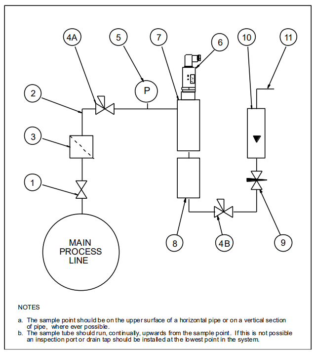 Piping Schematic Component Index
1、Sample Isolation Valve – This is a recommended item as it allows access to the sample systemwithout interrupting the main process line.
2、Sample Tube – This should be stainless steel for dry air or gas applications but copper or carbonsteel can be used where wetter gases are to be measured. If any section of the sample tube must beflexible then PTFE should be used. In most cases, 3mm OD (1/8”) is sufficient as it provides goodsystem response time within minimum flow. 6mm OD (1/4”) tube can be used where pressuredrops across the 3mm tube are too high.
3、Filter Unit – A filter unit is recommended when the samples are likely to contain particulate matter.If the air/gas sample contains heavy hydrocarbon condensate, the filter must be of the coalescingtype with a drain. The filter unit should be positioned as close to the sample point as practical.
4、Pressure Reduction Valve or Pressure Regulator – If the sample is to be measured at atmosphericpressure then the valve 4A should be fitted and 4B omitted from the system. If the sample is to bemeasured, at full line pressure and the exhaust vented to atmosphere, then valve 4B should befitted and 4A omitted from the system. If measurements are to be taken at full line pressure and thesample is to be returned to a part of the main line or a vent, which is at a pressure higher thanatmospheric, and the input to that line needs a controlled pressure then both 4A and 4B will berequired.
5、Sample Pressure Gauge – This is not a critical part of the moisture measurement but may berequired if Dew/Frost point measurements are to be made at higher than atmospheric pressure.
6、Measuring Transmitter, see “Appendix A – Model PDT with Connector, General Arrangement”.
7、 Transmitter Holder, see “Appendix B – Transmitter Holder General Arrangement”.
8、Desiccant Chamber – This item is required when the sampling is to be intermittent. When installedit prevents the ingress of wet air to the sample system, while the sample is not flowing, improvingthe response time.
9、Flow Control Valve – This can be a separate item or combined with the flow indicator.
10、 Flow Indicator – The recommended sample flow is 2 to 3 litres per minute.
11、Sample Exhaust – The exhaust can be vented to atmosphere or returned to the process line asdiscussed above.
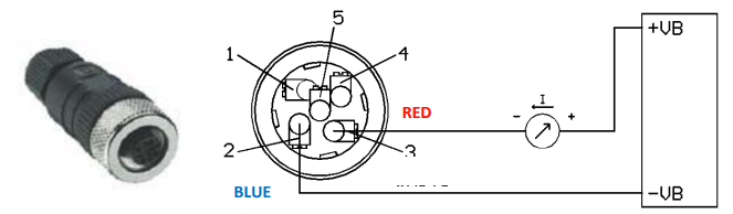
Wiring
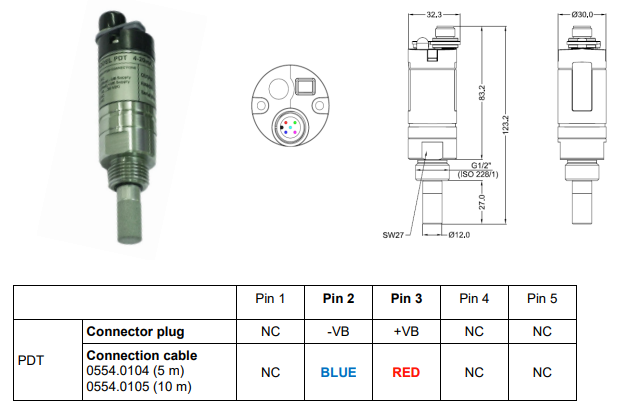
| -VB |
Negative supply voltage |
| +VB |
Positive supply voltage 10-30 VDC smoothed |
| NC |
Not connected |
M12 connector plug
If no connection cable is ordered, the sensor will be supplied with a M12 connector plug. The usercan connect the supply and signal cables as indicated in the connection diagram.
Installing and Commissioning the Model PDT Transmitter
It is advisable to carry out an initial purge of the sample loop, before installing the transmitter, inorder to reduce the possibility of sensor damage on start-up.
Open the inlet isolation valve slowly, until asmall flow of air/gas at atmospheric pressure flows through the inlet pipe work to the transmitterholder and exhausts through the sensor entry port of the transmitter holder.
Allow this purge to continue for about 15 to 20 minutes to remove any residual moisture from thesample pipe work and components.
Close the inlet isolation valve and install the transmitter into the transmitter holder. Locate andsecure the cable connector in position on the transmitter. Use the locking screw in order to affecta weatherproof seal.
Open the inlet valve slowly again and, by opening all valves after the transmitter holder, allow alow-pressure purge through the whole sample system. (Note. If a closed by-pass loop is installed,this section of the procedure is not possible).
Set the required pressures and flows within the sample loop.
This completes the installation and commissioning but, on initial start-up, it could take severalhours for the system to reach equilibrium.
Warning
- Do not exceed a pressure of 5,000kPa (50 bar) with the standard version.
- Observe the operating ranges of the sensor. The probes are damaged if they are overheated.
- Observe maximum storage and transport temperature as well as maximum operatingtemperature (i.e. protect the instrument from direct sunlight).
- Important: Before installation, bleed compressed air systems in order to remove condensateand particles to avoid contamination.


